Round Type Flow Meter
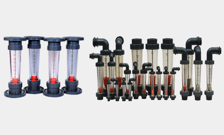
Rotameter
Description
A rotameter is device that measures the flow rate of fuild in a closed tube. It belongs to a class of meters called variable area meters, which measure flow rate by allowing the cross-sectional area the fuild travels through, to vary, causing a measurable effect.
Principle of Operation
The rotameter's operation is based on the variable area principle: fluid flow raises a float in a tapered tube, increasing the area for passage of the fulid. The greater the flow, the higher the float is raised. The height of the float is directly propotional to the flow rate. With liquids, the float is raised by a combination of the buoyancy of the liquid and the velocity head of the fuild. The float moves up or down in the tube in proportion to the fuild flow rate and the annular area between the float and tube wall. The float reaches a stable position in the tube when the upward force exerted by the flowing fluid equals the downward gravitational force exerted by the weight of the float. A change in flowrate upsets this balance of froces. The float then moves up or down, changing the annular area until it again reachesa position where the forcesare in equilibrium. to satisfy th force equation, the rotameter float assumes a distinct position for every constant flowrate. However, it is important to note that because the float position is gravity dependent, rotameters must be vertically oriented and mounted..
Materials of Rotameter Parts :
- Joint Fittings: PVC
- Male & Female Thread: PVC
- Taper Tube: PC
- Floats: ABS
Connection Mode of Rotameter :
- Intubation connection
- Internal & external thread
- Panel mounting
Technical Data
| Model | DN(mm) | Range | Accuracy | ° C | MPa | |
|---|---|---|---|---|---|---|
| LPH | CUM | |||||
| FM 15 | 15 | 10-100 | ± 4% | 0-60 | ≤ 1.0 | |
| 20-200 | ||||||
| 50-500 | ||||||
| 200-1200 | ||||||
| CWC 15 | 15 | 25-250 | ||||
| 40-400 | ||||||
| 60-600 | ||||||
| 120-1200 | ||||||
| CWC 25 | 25 | 100-1000 | 0.1 - 1.0 | |||
| 160-160 | 0.16 - 1.6 | |||||
| 250-2500 | 0.25 - 2.5 | |||||
| CWC 32 | 32 | 400-4000 | 0.4 - 4.0 | |||
| 600-6000 | 0.6 - 6.0 | |||||
| CWC 40 | 40 | 600-6000 | 0.6 - 6.0 | |||
| 800-8000 | 0.8 - 8.0 | |||||
| 1000-10000 | 1.0 - 10.0 | |||||
| CWC 50 | 50 | 1000-10000 | 1.0 - 10.0 | |||
| 1600-16000 | 1.6 - 16.0 | |||||
| CWC 65 | 65 | 5 - 25 | ||||
| 8 - 40 | ||||||
| 12 - 60 | ||||||
| CWC 100 | 100 | 5 - 25 | ||||
| 10 - 90 | ||||||
| CWC 125 | 125 | 12 - 120 | ||||
| 20 - 200 | ||||||
Installation Dimensions :
| Model | L | D | L3 | E | L4 | F | 5 |
|---|---|---|---|---|---|---|---|
| FM 15 | 100 | 40 | 145 | 1/2" BSP | 155 | 40 | 33 |
| CWC 15 | 160 | 50 | 210 | 1/2" BSP | 230 | 56 | 27 |
| CWC 25 | 17 | 59 | 225 | 3/4" BSP | 275 | 71 | 28 |
| CWC 32 | 225 | 72 | 290 | 1" BSP | 345 | 86 | 35 |
| CWC 40 | 225 | 78 | 320 | 1 1/2" BSP | 390 | 100 | 35 |
| CWC 50 | 290 | 98 | 370 | 2" BSP | 440 | 109 | 40 |
| CWC 65 | 325 | 120 | 420 | 2 1/2" BSP |
Intubation connection, internal and thread and panel mounting.
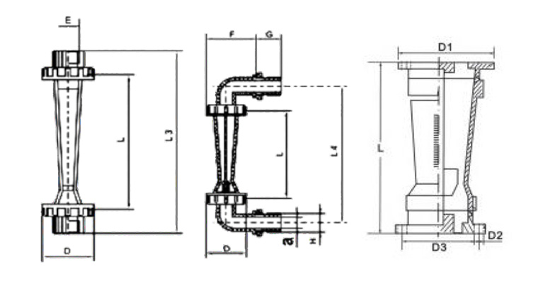
| Model | L | D1 | D2 | D3 |
|---|---|---|---|---|
| CWC - 100 | 555 | 215 | Ø 17 X 8 | 180 |
| CWC - 125 | 555 | 250 | Ø 17 X 8 | 210 |